How to identify terminal 30 pins
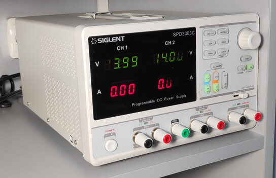
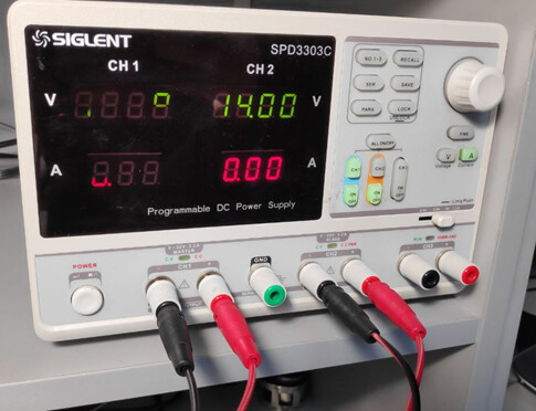
You’ll need a programmable power supply for this. For example, something like this:
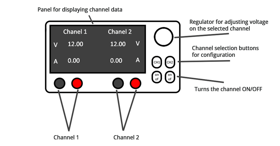
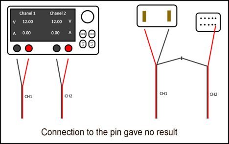
Control panel diagram:
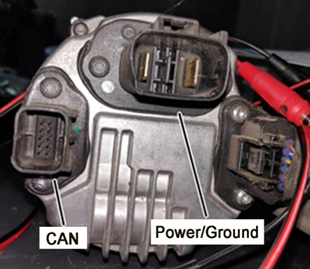
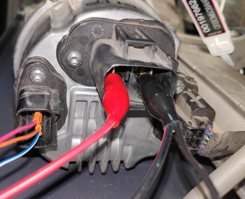
Example of a steering rack connector.
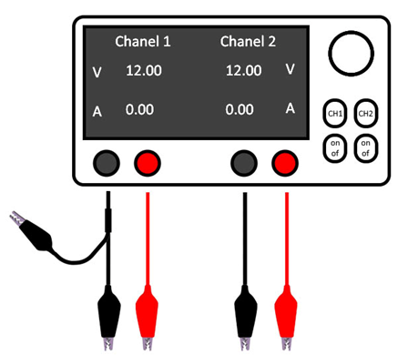
- Set both channels of the power supply to 12 or 14 volts. Then connect wires with alligator clips to each channel.
Note: For Channel 1, use a black (negative) wire with two alligator clips.
- Make sure both channels are turned on. Connect the positive wire from Channel 1 to any pin in the Power/Ground connector. Connect the negative wire from Channel 1 to a second pin in the same connector. Then connect the negative wire from Channel 2 to the unused ground wire from Channel 1 (this way, both channels share a common ground).
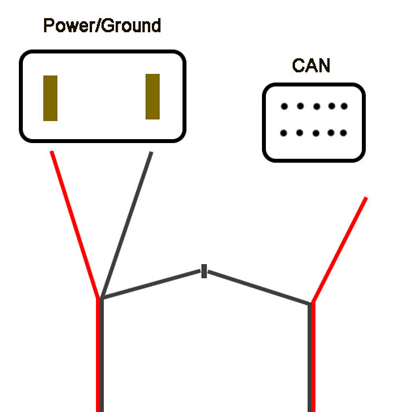
- Now, take the positive wire from Channel 2 and touch it to the pins in the CAN connector one by one.
• If the current (amperage) on Channel 2 increases, you’ve found the K15 pin.
• If not, swap the polarity (positive and negative) on the power connector and try the procedure again.
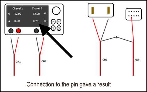

Once you find the K15 pin, leave the positive of the Channel 2 connected to it to move on to the next step.
How to Identify CAN High and CAN Low Pins
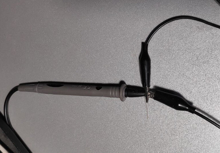
Now you’ll need a digital multimeter. For example, something like this:
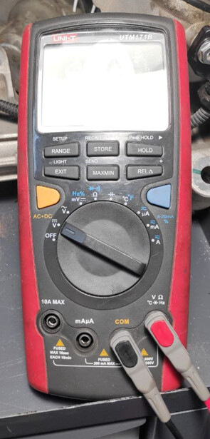
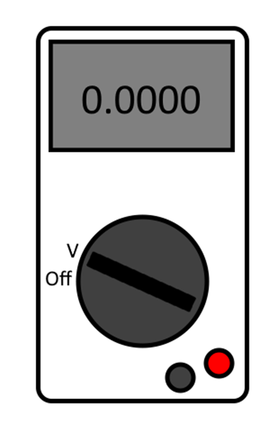
Set the multimeter to DC voltage measurement mode and connect two wires to it — one to the positive input and one to the negative.
- Connect the negative probe of the multimeter to the common ground wire from the power supply.
- Use the positive probe to touch the pins in the CAN connector one by one, and watch the multimeter readings:
• If the reading is close to 2.9V, that pin is CAN Hi

• If the reading is close to 2.0V, that pin is CAN Low
